
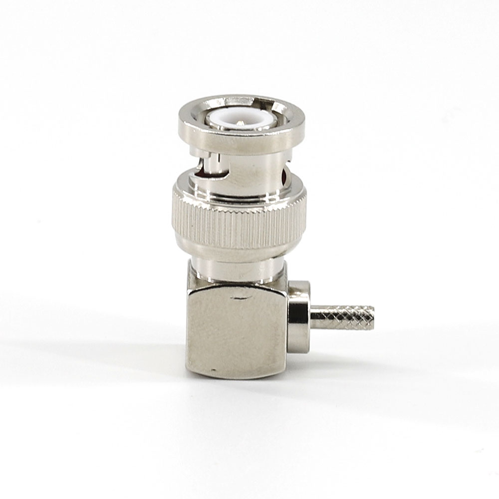
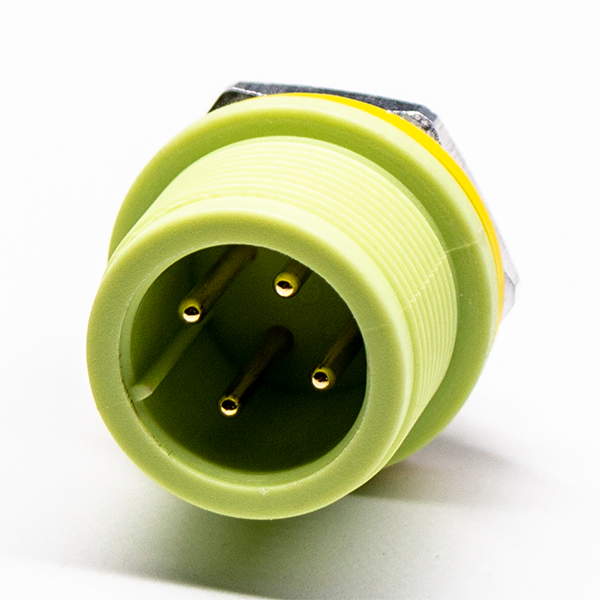
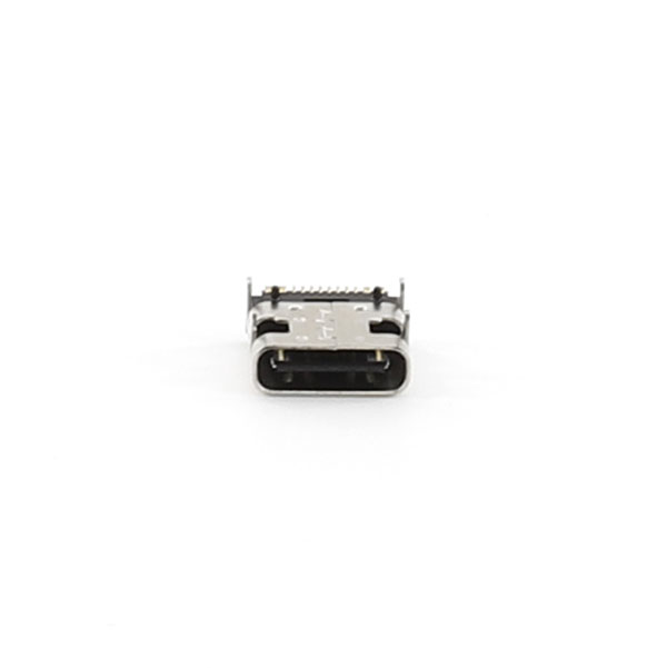
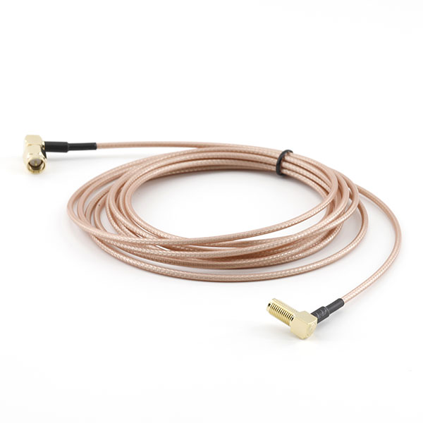












Common connectors for electronic devices include board-to-board connectors, wire-to-board connectors, wire-to-wire connectors, pin header and socket connectors, FPC connectors, USB connectors, power connectors, and industrial connectors, among others.
Board-to-board connectors are used to connect two PCBs. They are compact, offer high data transfer speeds, and save space, making them widely used in smart devices, communications equipment, and industrial electronics.
Wire-to-board connectors are used to connect wire harnesses to PCBs. They offer flexible installation options and are commonly used in control equipment, home appliances, automotive electronics, and industrial equipment.
FPC connectors are specifically designed to connect flexible printed circuit boards. They are lightweight, space-saving, and highly reliable, and are commonly used in displays, smart devices, and precision electronic equipment.
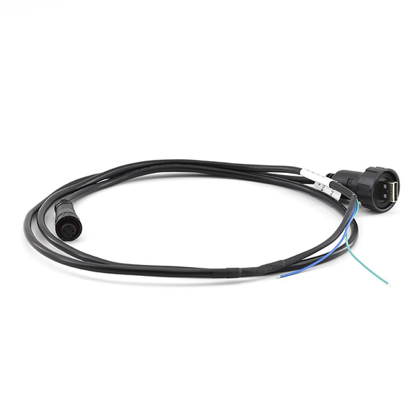
Industrial connectors are characterized by high reliability, strong environmental resistance, and a high protection rating, making them suitable for industrial automation, mechanical equipment, and outdoor electronic systems.
Yes. Connectors can be customized according to customer requirements in terms of pin count, pitch, structural dimensions, materials, plating methods, and connection types.
The selection should be based on equipment space, current requirements, signal type, installation method, operating environment, and connection lifespan.
Common configurations include pin-type, socket-type, latch-type, snap-fit, board-end, and wire-end, among others.
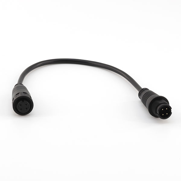
The male connector typically has pins or blades, while the female connector has a corresponding socket structure; the two are used together to establish an electrical connection.
The number of pins refers to the number of contact points inside the connector that can transmit signals or power; different applications require different pin count specifications.
Pitch refers to the distance between adjacent terminals on a connector; common specifications include 0.5 mm, 1.0 mm, 2.0 mm, and 2.54 mm.
Micro connectors are compact, saving space inside devices, and are suitable for smart wearables, mobile devices, and precision electronic equipment.
The latch mechanism enhances connection stability and prevents the connection from coming loose due to equipment vibration or movement.
Common mounting methods include PCB soldering, plug-in mounting, crimping, surface-mount technology (SMT), and through-hole mounting (DIP).
SMT connectors are manufactured using surface-mount technology, making them suitable for automated production. They offer advantages such as high installation efficiency and a small footprint.
DIP connectors are inserted into PCB holes via their pins and soldered in place, offering high mechanical strength and a stable connection.
During installation, check the orientation, pin positions, solder quality, and insertion/removal force to prevent damage to the terminals.
Different connector designs have different insertion/removal lifespans; the appropriate model should be selected based on the equipment's maintenance requirements.
Key parameters include rated current, rated voltage, contact resistance, insulation resistance, mating cycle life, operating temperature, and others.
The rated current refers to the maximum operating current that the connector can transmit stably over the long term; it should be selected based on the device's power consumption.
The lower the contact resistance, the less signal and current transmission loss there is, and the more stable the connection.
Connectors made of different materials and with different designs have varying temperature ranges; common products can meet the temperature requirements of industrial environments.
If used outdoors or in harsh environments, choose waterproof connectors with a protection rating (such as IP65 or IP67).
Common materials include copper alloy terminals, plastic-insulated housings, and metal shielding structures; different materials affect electrical conductivity and durability.